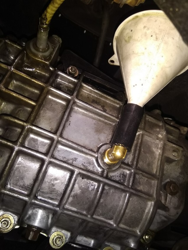
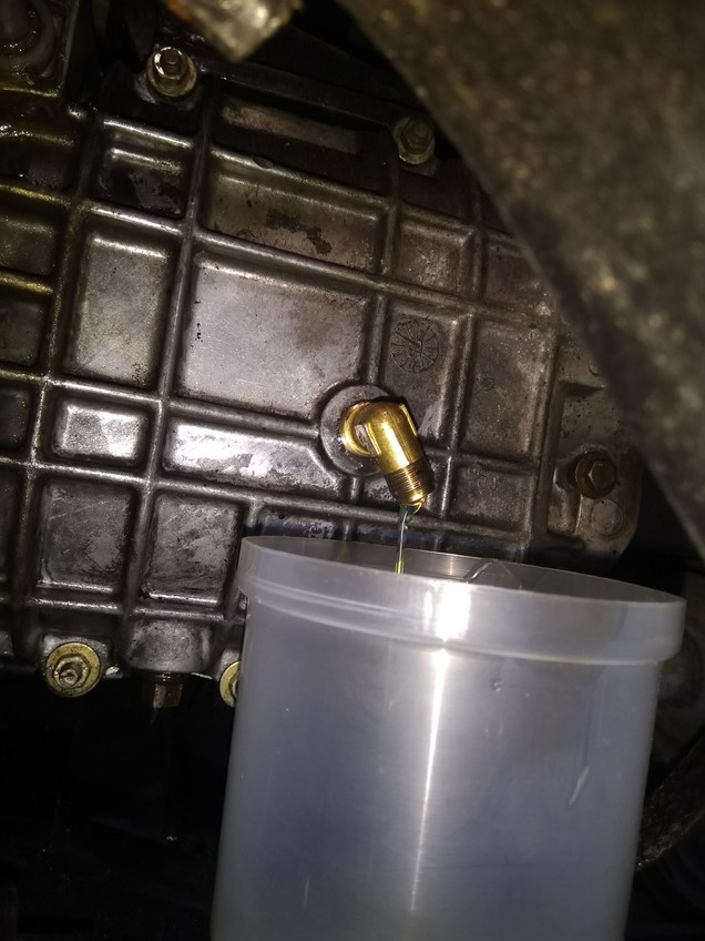
Gearbox Oil-Filler
G3/8 inch conical 90° angle fitting
Fill oil without a mess 🙂
According to the manual there are 3 liters required – filler hole gives the level. I fill a little bit more – then turn the angle fitting and let the excess oil run off – then unscrew the fitting and quickly close it with the bolt – the oil level is now about 3 mm higher than in the manual required

Oil drain screw & copper washer
To get the oil drain screw tight, you have to tighten it relatively strongly, especially if you use normal copper washer. A normal copper washer is usually not soft enough and must first be softened (heat to cherry red, then quench in water).
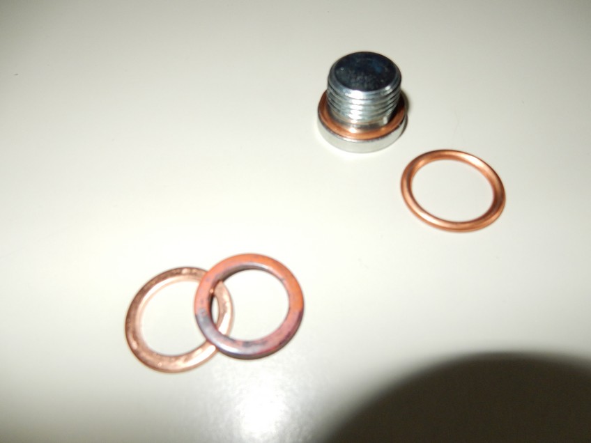
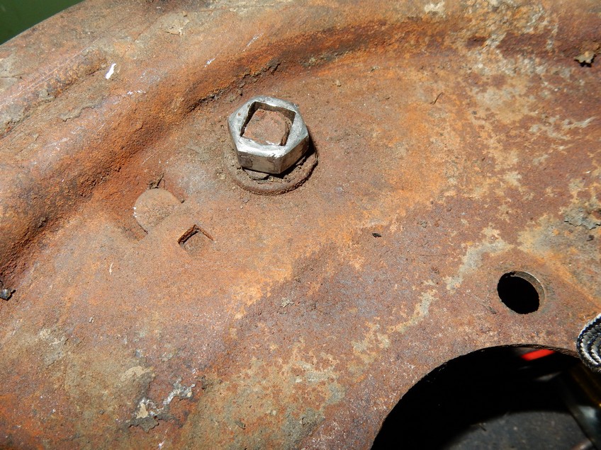
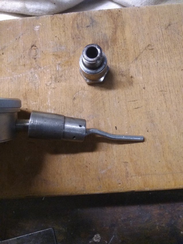
Right drain screw 18mm and modern compound seal (18mm)
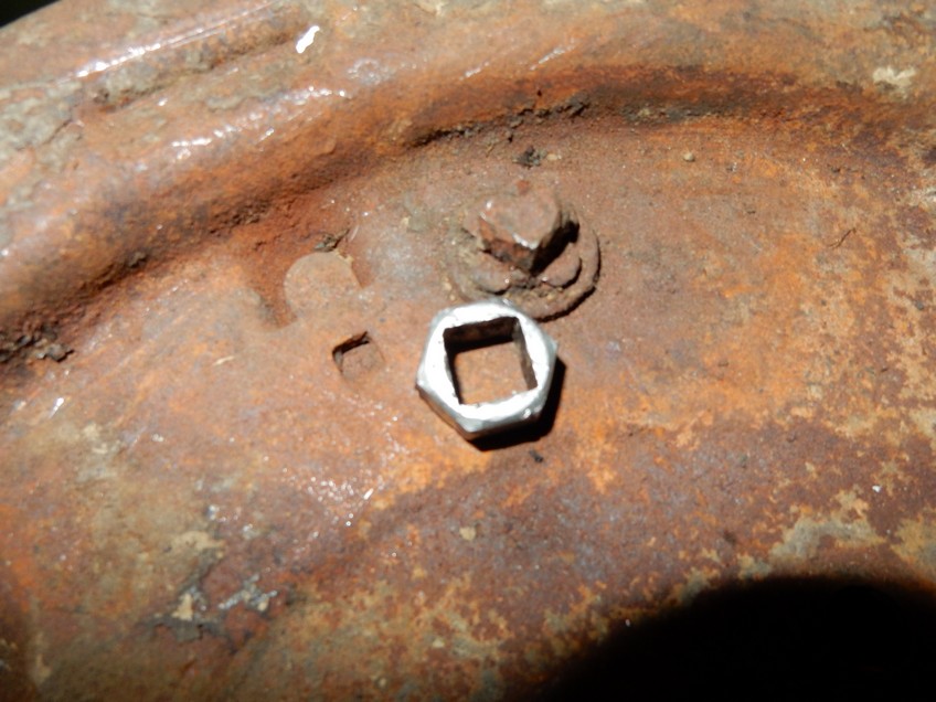
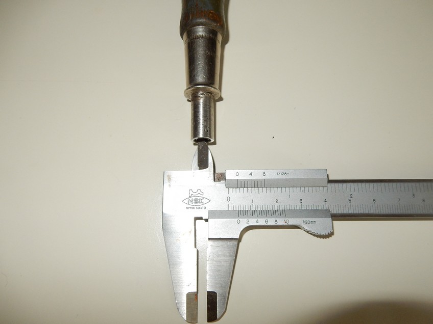
The oil drain screw (16mm) of my couchette is smaller than usual (18mm / 10mm) and has an 8mm square – I made a 4-edged nut out of an M16 8. 8 screw – so the screw is easy to loosen.
Left 8mm 4-edged key, right 10mm 4-edged key

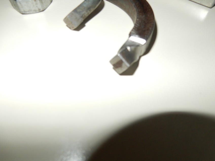

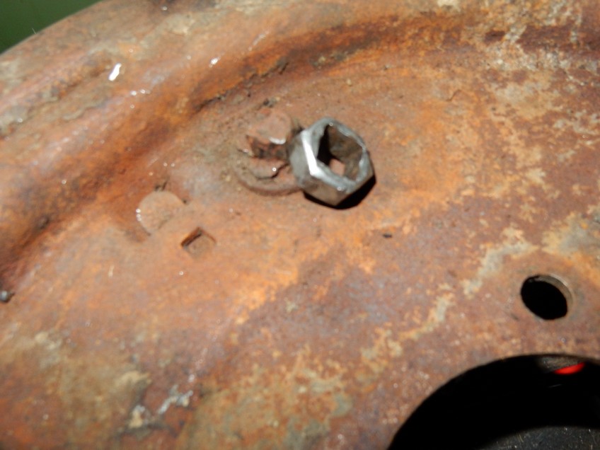
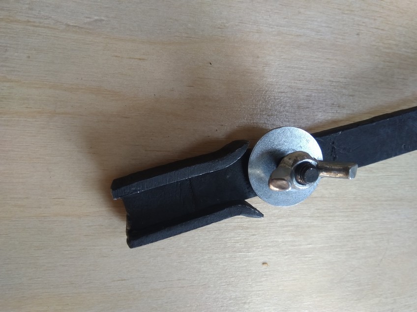
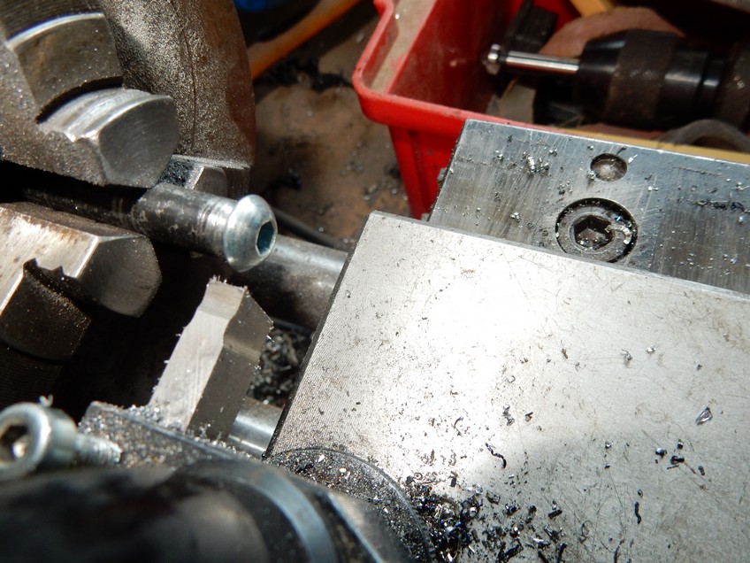
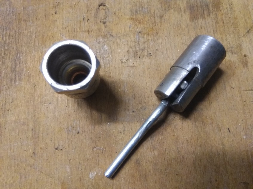
Adapter for the Break-Excenters
The excenters of the brake jaws can rust and are then hardly moveable despite creeping oil. With the fork wrench you like to break the 4-edge.
With an M10 nut and a small triangular file you can easily make an adapter with 10mm inner square (key width 17mm)
Tool for Ignition Distributor
Goes perfect with the tool role, tool sizes 10 & 11 mm


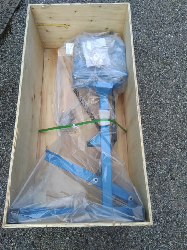
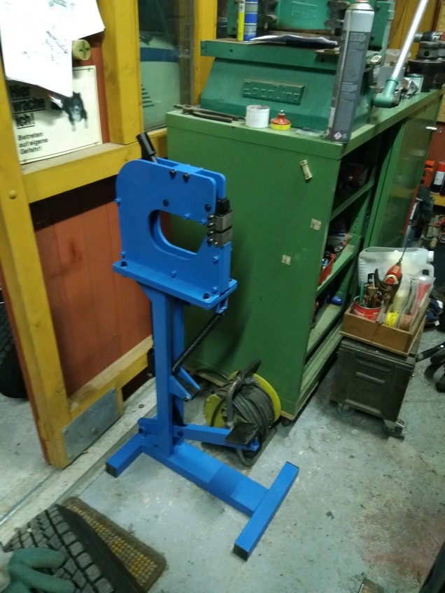
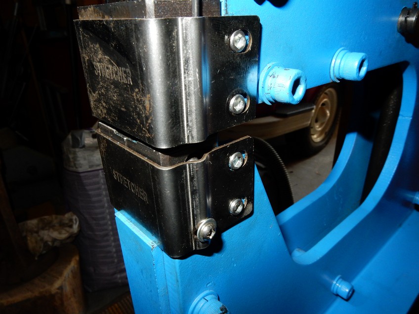
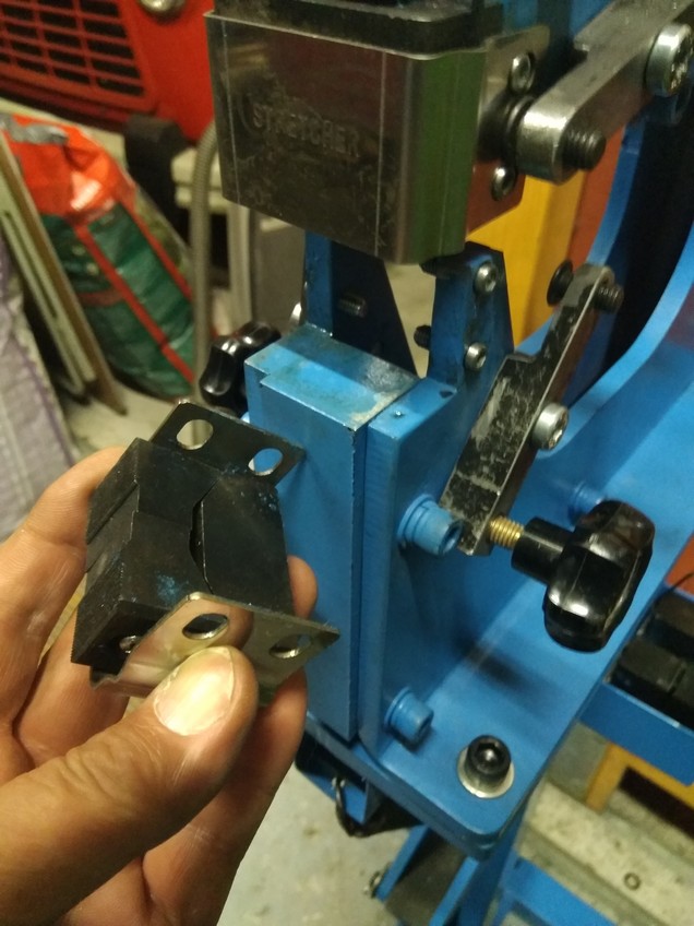
Stretch-Shrink Tool
The stretch-shrink tool with stand has a pair of inserts for stretching and shrinking. The quality is quite good and the inserts are very exactly produced. Unlike the other devices, the base body is not made in iron cast, but screwed out of 10mm steel sheet
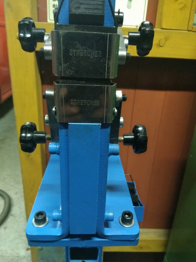
For the tool change, 8 screws must be loosened and completely removed. Since this can be very nasty, I have made a quick-changer device.
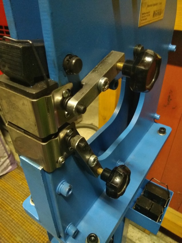
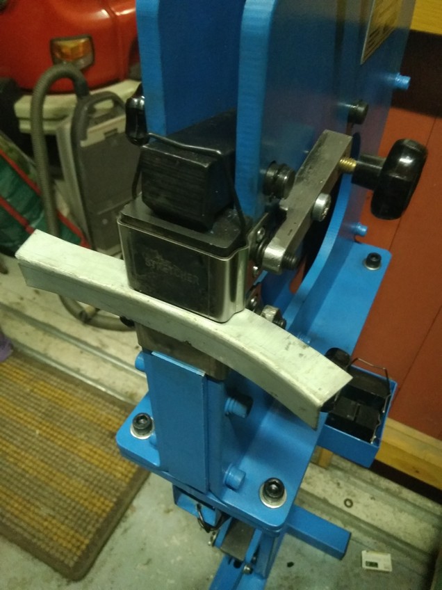
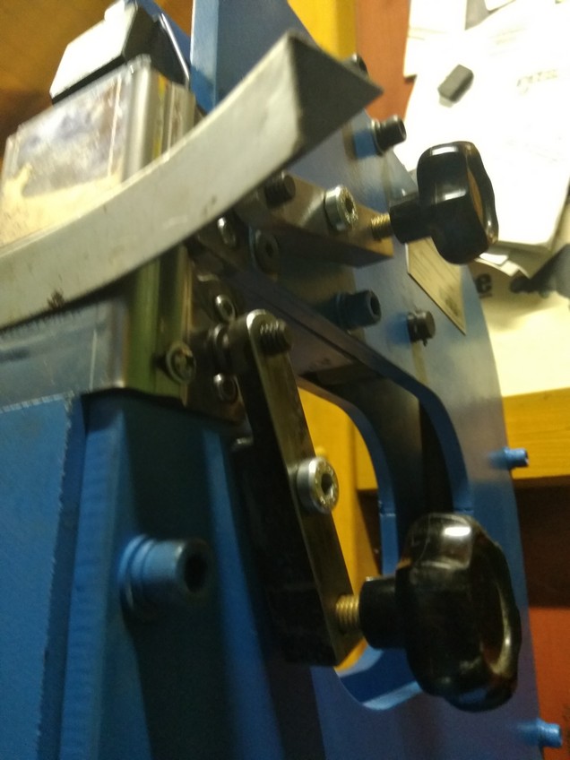
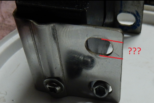
I replaced the 8 screws with pin screws. The pin screws give the position. The 4 tensioners are easy to remove manually without a tool key – the insert plates can then be “clicked out” / “clicked in. ”
Let’s see if the clamping force of the 4 tensioners is strong enough when in full operation – if so, the long holes in the insert plates could be opened into slots – then the insert change would be even faster
The tool is from HBM Machines in Holland – for about the same price a double machine (also with stand) is available – so there is no need to change tools – but it is not possible to process larger sheets. A similar double tool is available at Stahlwerk


Valve Mounting Tool
For the 810 heads, I made an valve mounting tool. The head is laid with the combustion chamber down on a piece of Multiplex board. The combustion chambers are modeled in beech wood and screwed to the panel – with this the valves are well positioned and cannot move when the spring is pressed downwards. For the 72mm head (the combustion chamber has a shallower depth) there is a plastic layer. The aluminium U-profile is mounted on the two long screws for fixing the rocker arms shaft (support has 20mm, the profile was found in scrap metal, it has 25×25 mm).
The valve lever is made of scrap metal, welded and fitted with a handle. When disassembling the valve it is sometimes a bit tricky to remove the valve clips upwards, it is better to do it with a magnet – on the other hand, the valve mounting is done schwupdiwupp 🙂


Tool for Valve Adjustment
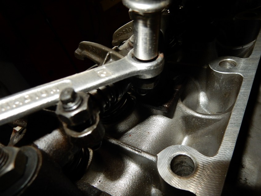
Instead of tool no. 13, an old screwdriver can be convertedinto an valve adjustment tool. Just cut off the screwdriver to an short length, insert a slot with the cutting disc, turn a bushing and glue in with Locktite.
The slot (4mm) should fit quite tight to the adjustment screw


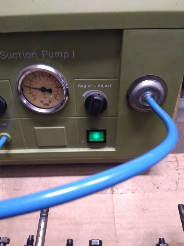
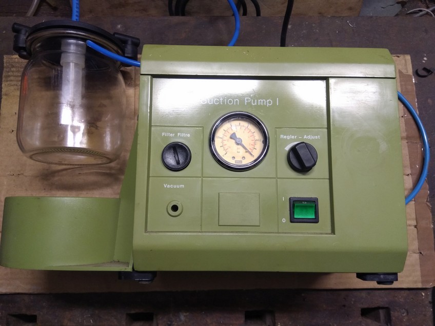
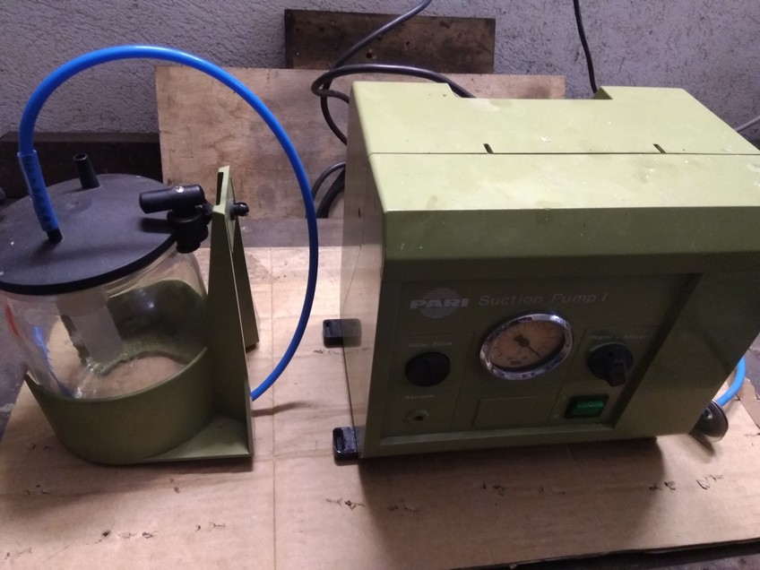
Valve close?
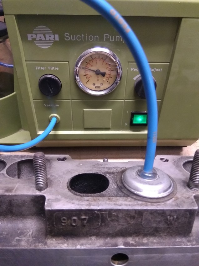
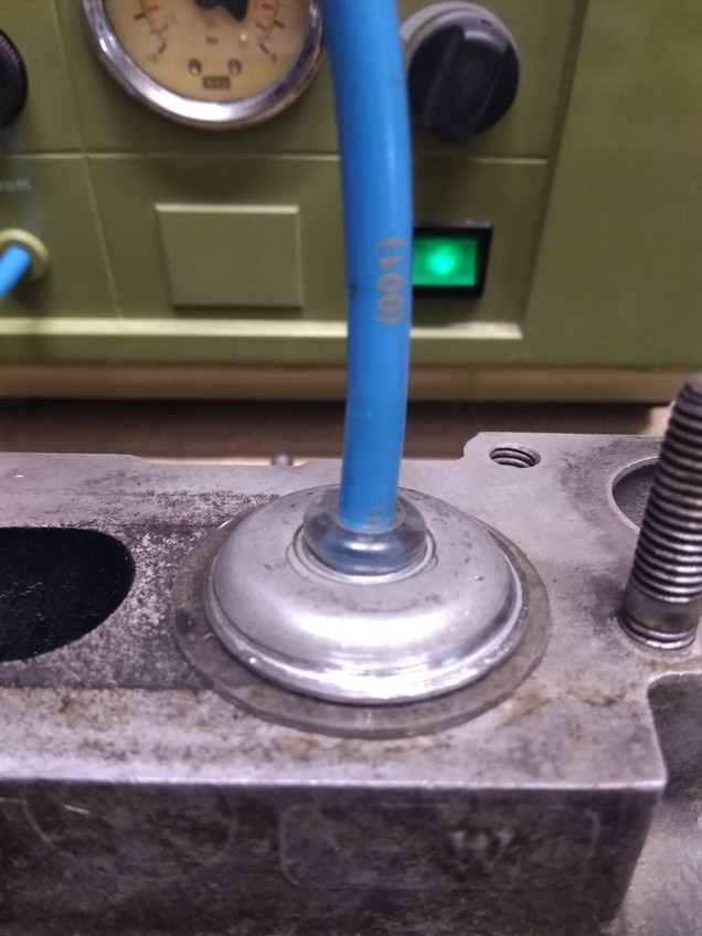
Base is an old laboratory vacuum suction device from Ebay. I use them, for example, for suction of brake fluid, or just to check the valves for leakage.
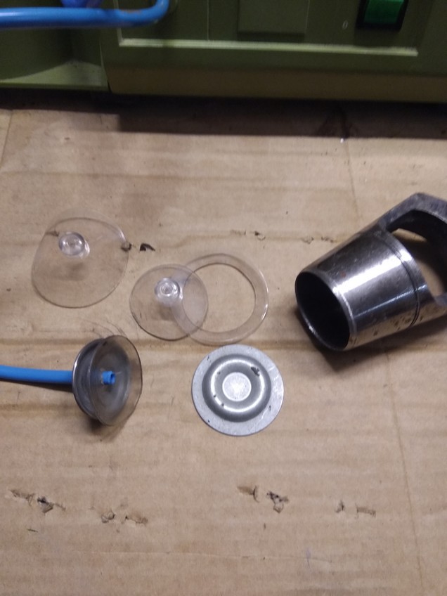
The suction cup has Ø 40mm the support washer approx Ø 30mm
The support washer acts like a suction bell and creates an annular sealing surface when pressed on. This works very well and gives you great safety when grinding the valves. Almost as a “calibration” you place the suction cup on a flat surface and you can read the maximum negative pressure – when grinding the valves the same value should be reached.


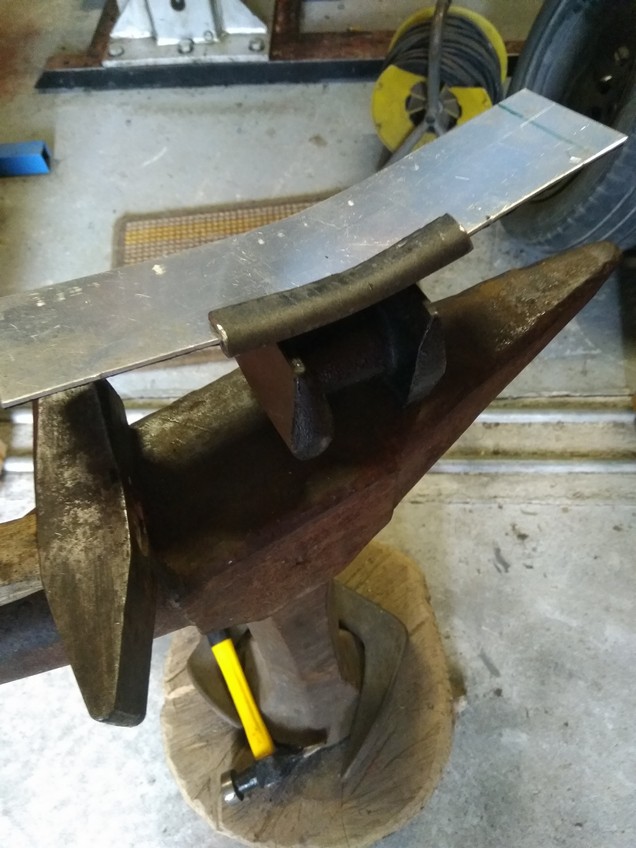
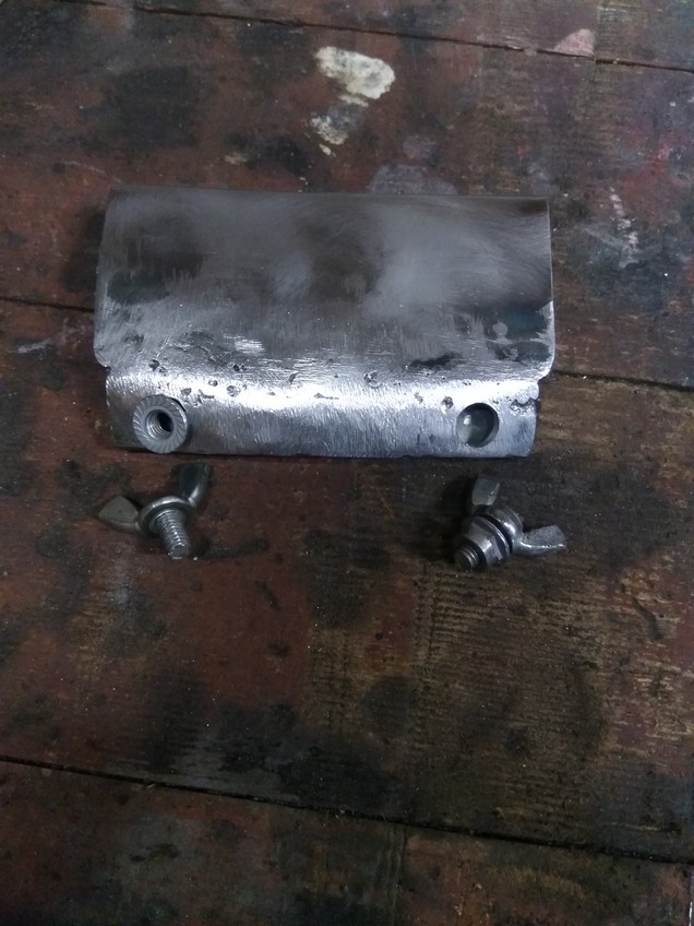
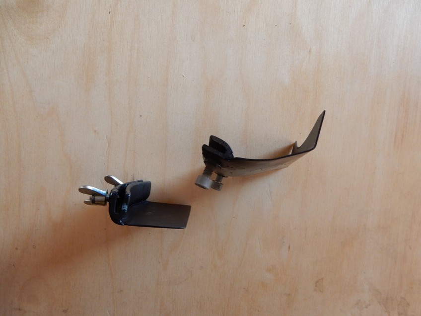
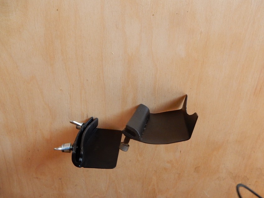
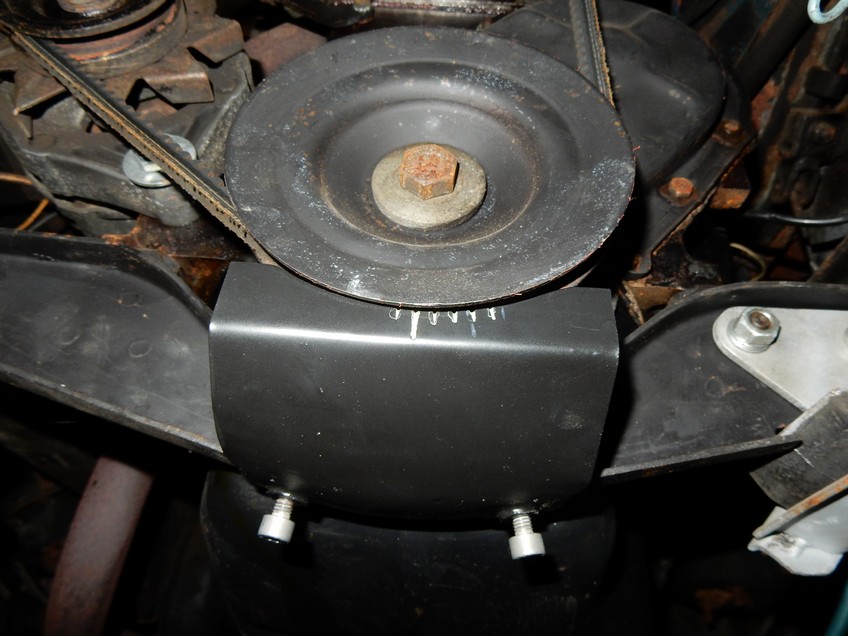
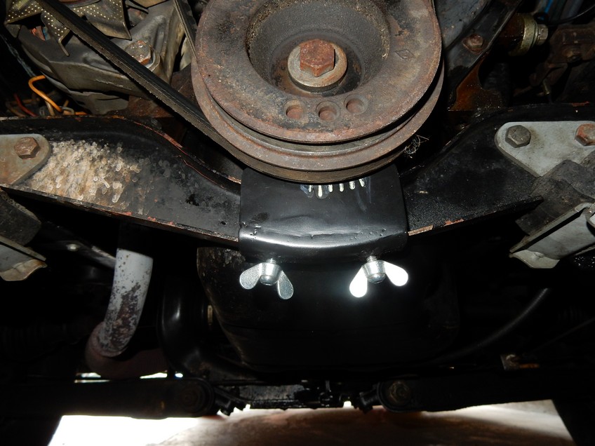
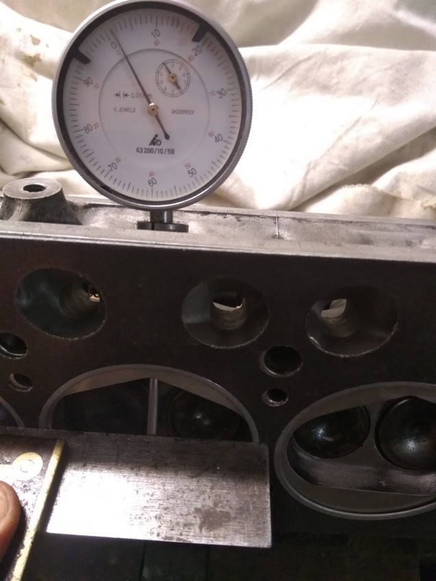
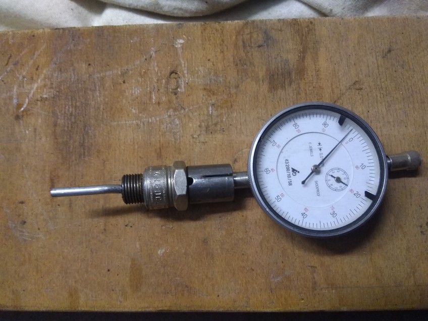
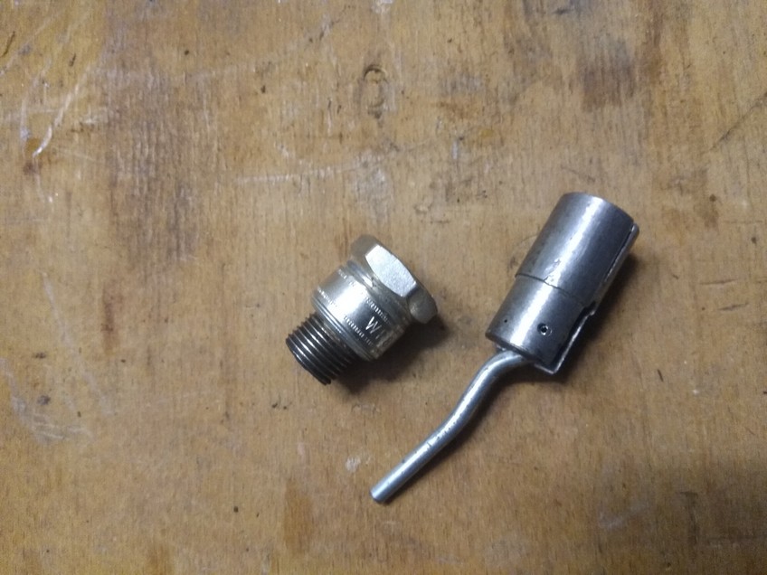
Jauge point morte haut
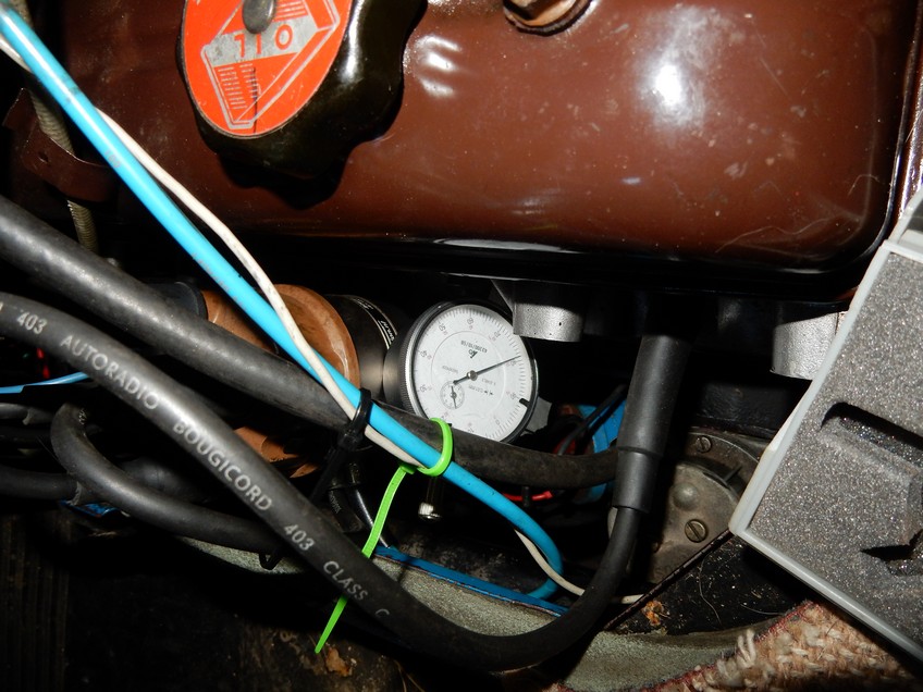


Ignition scale
On the Estafette motor, an ignition scale is usually attached to the steering cover above the puley. With the stroboscope gun it is very dificult to check the ignition time here.
(and with the R15 engine of my couchette there is no ignition scale at all)
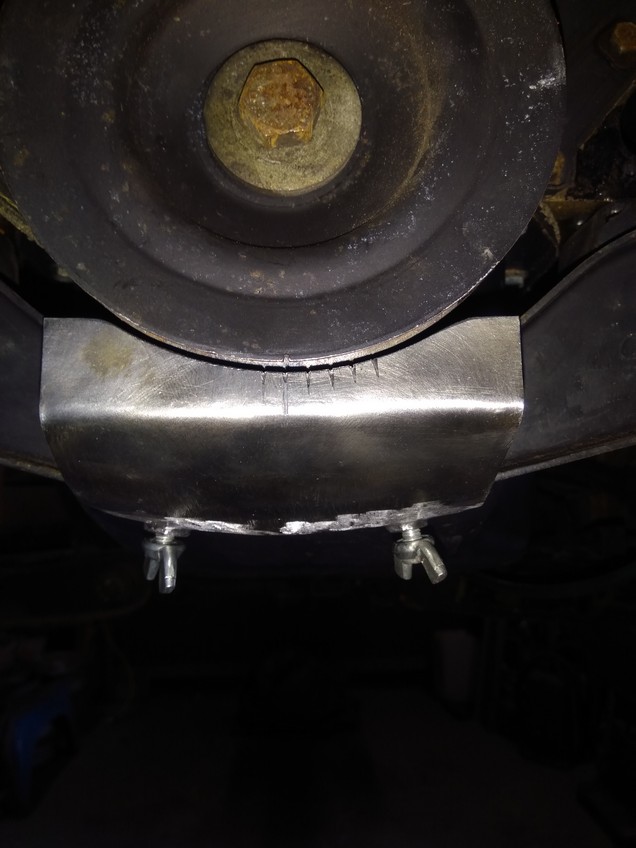
Wouldn’t it be a lot easier if the ignition scale was below the Puley?
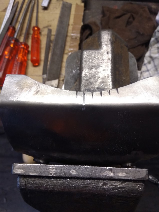
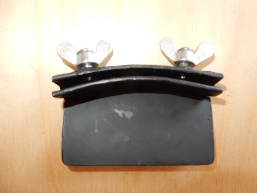
Since such an ignition scale is mounted in flight, i. e. not fixed, of course, the engine must always be set to upper dead center first in order to be able to fix the scale exactly – after that the handling with the stroboscope is much easier
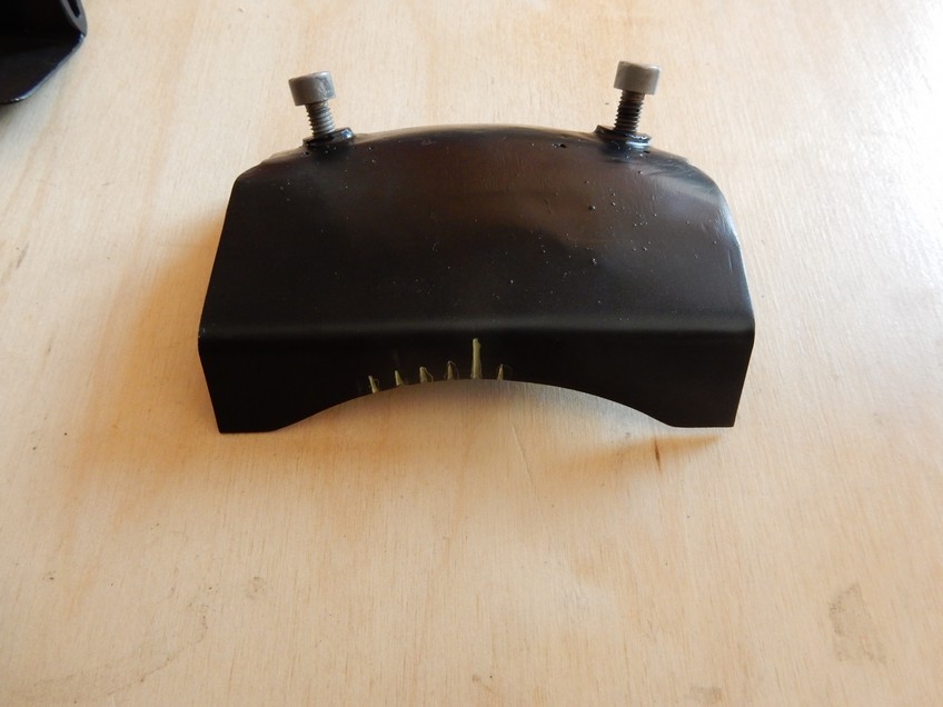
I set the scale to 5° segments (notch distance approx. 5. 8 mm at Ø330 )
- Entering 3′ gear
- Remove spark plug cylinder 3 (or 2)
- Set cylinder 3 (or 2) to upper dead center by moving the Estafette slowly forward
- Take out gear and fix the handbrake
- Reinstall spark plug 3 (or 2)
- Align ignition scale at the 0° notch and screw it in place
- Keep the engine running and check the ignition time at idle